


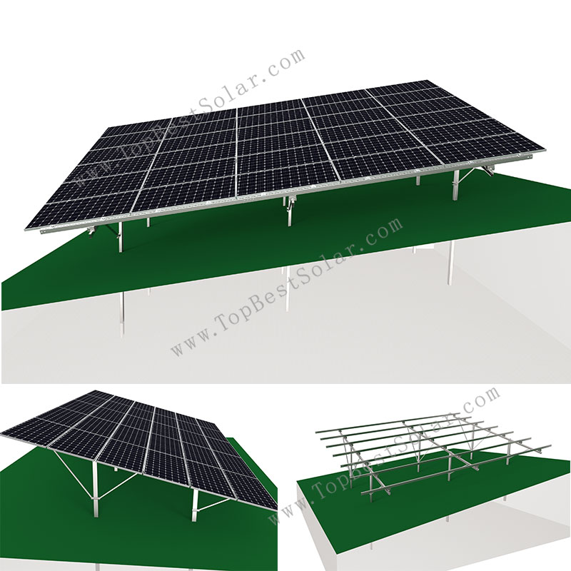
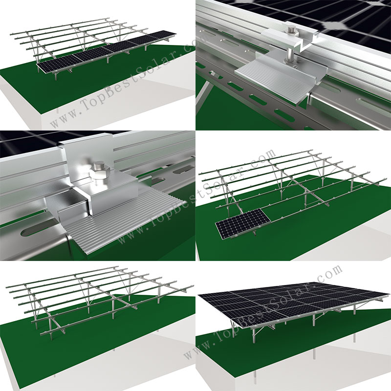
Solar Sloping Ground Mounts
Model: SPC-GC-6H-2PW-EW
Installation Site: Ramp Ground
Material: Aluminum alloy, HDG steel;
Tilt Angle: 0° to 20°
PV Module: Framed, Frameless
Module Layout: As Designed
PV Orientation: Portrait, Landscape
Wind Load: 60 m/s
Snow Load: 1.4 KN/M2
Warranty: 10 Years


Product Description:
As professional innovative PV mounting solution factory, SPC solar release ground rack for slope hill.
Usually the ground should be levelled before pv module installation.
The even land helps maximize power system output.
But if we meet mountain or high hill, it’s not economic or possible make land even.
Solar ground rack on slope hill site would be very important mounting struture in ramp topography.
Generally sloping orientation can be divided in two types:
(1) South-North slope, our engineer will control row spacing and dense layout base on project terrain;
(2) East-West slope, it’s the most challenge and should optimized efficient array for constructioin;
Our pv ground racking system can be suitable for both kinds of directions.
Software analysis is recommended for large scale solar project, it helps reduce project material and labor cost.
Advantages of this solar ground racking for hill:
1) Suitable for 0° – 20° terrain variances;
2) Can be mounted on all slope directions;
3) Cost effective and safe sloping mounting solutions;
4) Quick install for solar ground mount racking for slope hill, SPC-GC-6H-2PW-EW.
As more and more flat and open terrain are occupied for solar power station, sloping ground / hill / mountain … will be new places for pv module installation.
Welcome to choose our solar sloping mounting system for your new generation power project.
- Description
-
Product Description:
As professional innovative PV mounting solution factory, SPC solar release ground rack for slope hill.
Usually the ground should be levelled before pv module installation.
The even land helps maximize power system output.
But if we meet mountain or high hill, it’s not economic or possible make land even.
Solar ground rack on slope hill site would be very important mounting struture in ramp topography.
Generally sloping orientation can be divided in two types:
(1) South-North slope, our engineer will control row spacing and dense layout base on project terrain;
(2) East-West slope, it’s the most challenge and should optimized efficient array for constructioin;
Our pv ground racking system can be suitable for both kinds of directions.
Software analysis is recommended for large scale solar project, it helps reduce project material and labor cost.
Advantages of this solar ground racking for hill:
1) Suitable for 0° – 20° terrain variances;
2) Can be mounted on all slope directions;
3) Cost effective and safe sloping mounting solutions;
4) Quick install for solar ground mount racking for slope hill, SPC-GC-6H-2PW-EW.
As more and more flat and open terrain are occupied for solar power station, sloping ground / hill / mountain … will be new places for pv module installation.
Welcome to choose our solar sloping mounting system for your new generation power project.
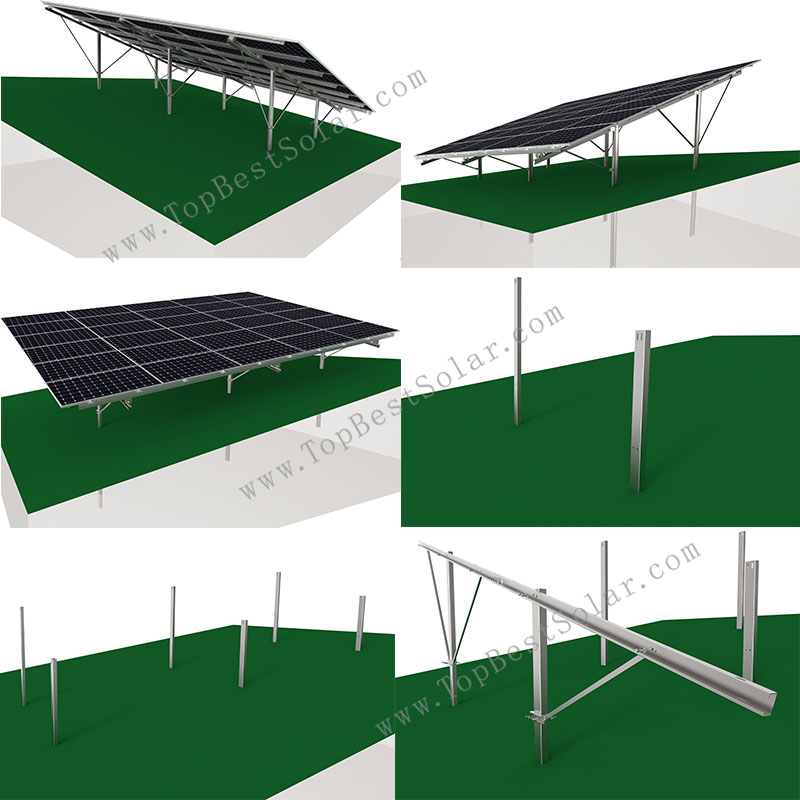
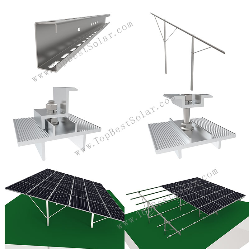
System composition:
1, Horizontal mid clamp;
2, Horizontal end clamp;
3,C80-T2 beam;
4,purlin components ;
5,East-west rotating parts;
6,Beam connecting plate ;
- Components
-
System composition:
1, Horizontal mid clamp;
2, Horizontal end clamp;
3,C80-T2 beam;
4,purlin components ;
5,East-west rotating parts;
6,Beam connecting plate ;
Solar Ground Slope Galvanized Steel Installation Instruction, SPC-GC-6H-2PW-EW
1. Tools preparation;
2. Materal preparation;
3.
installation steps
3.1
Basic installation
sort out the ground, clean up the on-site installation site to facilitate measurement and installation, etc.
3.1.2
As following picture shows, according to the site drawings, the ground slopes 8 degrees in the southwest direction, which corresponds to a slope of 5.66 degrees in the east-west direction and 5.66 degrees in the north-south direction. The length of the C-shaped column, which is relatively short in the south direction is L2700mm, and the vertical penetration depth is L1773mm during construction, and the ground is exposed L927mm. The length of the rear column is 3200, and the horizontal distance between the two columns is 2705mm and the height difference is 725mm during construction. The distance in the east-west direction along the slope is 3300mm, and along the horizontal direction is 3284mm.
Note: A special piling machine must be used for piling. Before piling, marking must be made on the construction site according to the east-west and north-south distances marked in the construction drawings. The columns in the east-west and north-south directions must be on the same horizontal line. During the piling process The piles must be driven in perpendicular to the ground. If they are skewed, they need to be corrected in time, and the height difference between the front and rear of the column is the same.
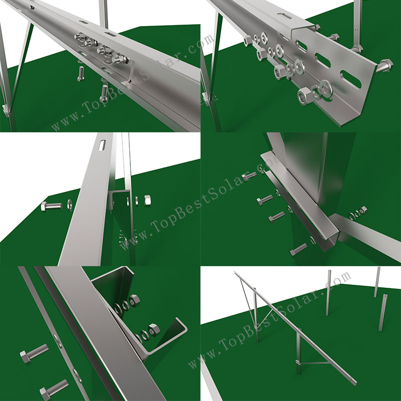
3.2
Installation of purlin and diagonal bracket
Use M10 * 25 bolt assemblies to fix the C80 purlin, L30 diagonal bracket and C60 diagonal bracket fixture to the column respectively.
According to the above steps, install the remaining C80 purlin on the column
3.3
Install East-west rotating parts
Install the east-west rotating parts on the purlin according to the position and size of the in the construction drawings. First fix the U-shaped base of the rotating part on the purlin with M10 inner hexagonal bolts, and the fixing holes on the purlin are elongated, which is convenient for adjustment. Then fix the upper rotating part to the U-shaped base with M12 outer hexagon bolts, and add a sleeve in the middle to prevent
the rotating part from being deformed by force.
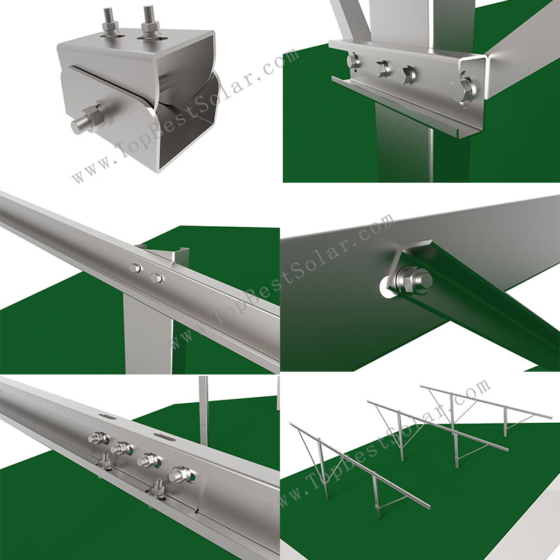
3.4 Install the beam
Connect the beams together with the L-shaped connecting plate according to the length of the beam on the construction drawing, and fix each joint with 6 M10*25 bolts. Each part is a long hole, so a little error is allowed, but the cumulative error cannot be too large. After the beams are spliced, they are fixed on the rotating parts with M10*25 square neck bolts. The length of the beams exposed to the longitudinal beams needs to be based on the construction drawings. The specific installation steps are as follows:
3.5 Install the mid clamp fixing plate, and install the fixing plate on the beam according to the drawing position with carriage bolts. There are 4 fixing points under each solar panel. The adjacent solar panels in the longitudinal middle position share 2 fixing plates. The flange nut fixes the mounting plate. Note: At the red box in the figure below, the bolts for the fixing plate installed on the side beam are relatively short. The bolts on the remaining middle part of the fixing plate are relatively long and should not be interchanged; the dimensions in the figure are for reference and can be adjusted according to the specific conditions of the
site, avoiding the position of the beam connecting plate.
Install solar panels
Put the solar panel on the installed fixing plate, install the mid & end clamp on the raised bolts to fix the solar panel, expose the shorter bolts to install the mid clamp, and expose the longer install the mid clamp.
- Installation
-
Solar Ground Slope Galvanized Steel Installation Instruction, SPC-GC-6H-2PW-EW
1. Tools preparation;
2. Materal preparation;
3.
installation steps3.1
Basic installationsort out the ground, clean up the on-site installation site to facilitate measurement and installation, etc.
3.1.2
As following picture shows, according to the site drawings, the ground slopes 8 degrees in the southwest direction, which corresponds to a slope of 5.66 degrees in the east-west direction and 5.66 degrees in the north-south direction. The length of the C-shaped column, which is relatively short in the south direction is L2700mm, and the vertical penetration depth is L1773mm during construction, and the ground is exposed L927mm. The length of the rear column is 3200, and the horizontal distance between the two columns is 2705mm and the height difference is 725mm during construction. The distance in the east-west direction along the slope is 3300mm, and along the horizontal direction is 3284mm.Note: A special piling machine must be used for piling. Before piling, marking must be made on the construction site according to the east-west and north-south distances marked in the construction drawings. The columns in the east-west and north-south directions must be on the same horizontal line. During the piling process The piles must be driven in perpendicular to the ground. If they are skewed, they need to be corrected in time, and the height difference between the front and rear of the column is the same.
3.2
Installation of purlin and diagonal bracketUse M10 * 25 bolt assemblies to fix the C80 purlin, L30 diagonal bracket and C60 diagonal bracket fixture to the column respectively.
According to the above steps, install the remaining C80 purlin on the column
3.3
Install East-west rotating partsInstall the east-west rotating parts on the purlin according to the position and size of the in the construction drawings. First fix the U-shaped base of the rotating part on the purlin with M10 inner hexagonal bolts, and the fixing holes on the purlin are elongated, which is convenient for adjustment. Then fix the upper rotating part to the U-shaped base with M12 outer hexagon bolts, and add a sleeve in the middle to prevent
the rotating part from being deformed by force.
3.4 Install the beam
Connect the beams together with the L-shaped connecting plate according to the length of the beam on the construction drawing, and fix each joint with 6 M10*25 bolts. Each part is a long hole, so a little error is allowed, but the cumulative error cannot be too large. After the beams are spliced, they are fixed on the rotating parts with M10*25 square neck bolts. The length of the beams exposed to the longitudinal beams needs to be based on the construction drawings. The specific installation steps are as follows:
3.5 Install the mid clamp fixing plate, and install the fixing plate on the beam according to the drawing position with carriage bolts. There are 4 fixing points under each solar panel. The adjacent solar panels in the longitudinal middle position share 2 fixing plates. The flange nut fixes the mounting plate. Note: At the red box in the figure below, the bolts for the fixing plate installed on the side beam are relatively short. The bolts on the remaining middle part of the fixing plate are relatively long and should not be interchanged; the dimensions in the figure are for reference and can be adjusted according to the specific conditions of the
site, avoiding the position of the beam connecting plate.
Install solar panels
Put the solar panel on the installed fixing plate, install the mid & end clamp on the raised bolts to fix the solar panel, expose the shorter bolts to install the mid clamp, and expose the longer install the mid clamp.