


Solar Ground Mounts
Model: SPC-GA20-4H-CA
Installation Site: Flat Ground
Material: Aluminum alloy, HDG steel;
Tilt Angle: 0° to 60°
PV Module: Framed, Frameless
Module Layout: As Designed
PV Orientation: Portrait, Landscape
Wind Load: 60 m/s
Snow Load: 2.0 KN/M2
Warranty: 10 Years


Product Description:
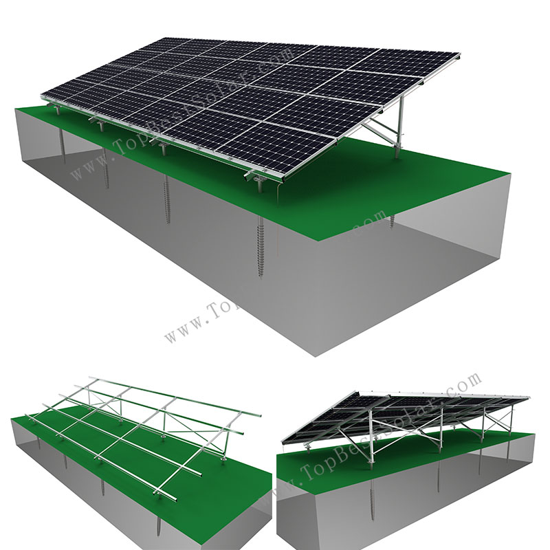
Solar ground racking system plays important role for PV module installation on flat terrain.
The mount racking model SPC-GA20-4H-CA is aluminum structure with fixed angle.
Most of foundation is suitable for ground screws, our engineer design with HDG steel piles for geological conditions.
With experience, we’ll match with proper pile type for various soil type like: stone, clay, sandy, silt or gravel …
But rammed post or concrete base are also can be choosen for this ground racking.
Advantages of this solar ground mount racking system:
1) Durablity for 20 years up, anti-corrosion;
2) 0° ~ 60° Tilt angle suitable;
3) Portrait / Landscape orientation for array;
4) 60m/s MAX for wind loading;
5) 2.0KN/M2 MAX for snow loading;
6) ASCE7-10; EN 1990:2002/A1:2005 Eurocode;AS 1170 Standards complies;
7) Heavy duty structure for ground mounts;
8) Great performance for different soil conditions;
9) Simple installation without drilling or welding;
Welcome to contact www.TopBestSolar.com for securing solar panel on the ground arrays.
- Description
-
Product Description:
Solar ground racking system plays important role for PV module installation on flat terrain.
The mount racking model SPC-GA20-4H-CA is aluminum structure with fixed angle.
Most of foundation is suitable for ground screws, our engineer design with HDG steel piles for geological conditions.
With experience, we’ll match with proper pile type for various soil type like: stone, clay, sandy, silt or gravel …
But rammed post or concrete base are also can be choosen for this ground racking.
Advantages of this solar ground mount racking system:
1) Durablity for 20 years up, anti-corrosion;
2) 0° ~ 60° Tilt angle suitable;
3) Portrait / Landscape orientation for array;
4) 60m/s MAX for wind loading;
5) 2.0KN/M2 MAX for snow loading;
6) ASCE7-10; EN 1990:2002/A1:2005 Eurocode;AS 1170 Standards complies;
7) Heavy duty structure for ground mounts;
8) Great performance for different soil conditions;
9) Simple installation without drilling or welding;
Welcome to contact www.TopBestSolar.com for securing solar panel on the ground arrays.
Components List of flat ground solar mounts:
① Basic bracket
② Steel rail
③ Rail splice
④ Back cross pipe
⑤ Mid clamp
⑥ End clamp
⑦ Base
⑧ Ground screw
- Components
-
Components List of flat ground solar mounts:
① Basic bracket
② Steel rail
③ Rail splice
④ Back cross pipe
⑤ Mid clamp
⑥ End clamp
⑦ Base
⑧ Ground screw
Installation steps for solar ground mount racking, SPC-GA20-4H-CA:
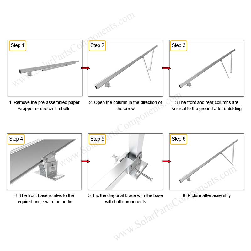
Step 1: Pre-assembly and installation of purlin.
When shipping, the factory has pre-assembled the purlin, jackets, columns, and grounding screws with bolts. After the bracket arrives on site, only need to open the pre-assembly, rotate the square tube in the direction on the drawing, and then remove the pre-assembled Bolts, lock the square tube on the base, and finally tighten all the bolts with a torque wrench.
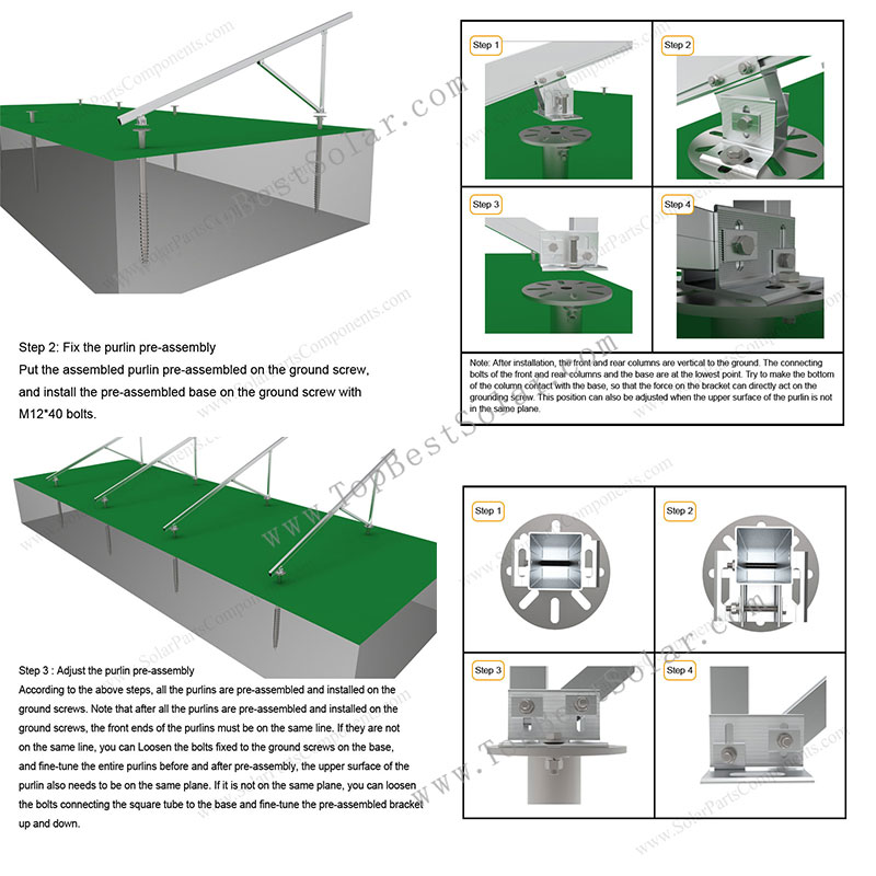
Step 2: Fix the purlin pre-assembly
Put the assembled purlin pre-assembled on the ground screw, and install the pre-assembled base on the ground screw with M12*40 bolts.
Note: After installation, the front and rear columns are vertical to the ground. The connecting bolts of the front and rear columns and the base are at the lowest point. Try to make the bottom of the column contact with the base, so that the force on the bracket can directly act on the grounding screw. This position can also be adjusted when the upper surface of the purlin is not in the same plane.
Step 3 Adjust the purlin pre-assembly
According to the above steps, all the purlins are pre-assembled and installed on the ground screws. Note that after all the purlins are pre-assembled and installed on the ground screws, the front ends of the purlins must be on the same line. If they are not on the same line, you can Loosen the bolts fixed to the ground screws on the base, and fine-tune the entire purlins before and after pre-assembly, the upper surface of the purlin also needs to be on the same plane. If it is not on the same plane, you can loosen the bolts connecting the square tube to the base and fine-tune the pre-assembled bracket up and down.
Step 4 install aluminum edge column
The aluminum edge column is installed on the rear vertical support square tube. The rear vertical square tube has pre-drilled holes. The aluminum edge column is fixed with M10 external hexagonal bolt components.
One square tube is installed on each of the front and back sides, and the two aluminum edge columns are cross-shaped, and one set is installed crosswise every other span.
Step 5 splicing beams
The steps of rail connection are as follows:
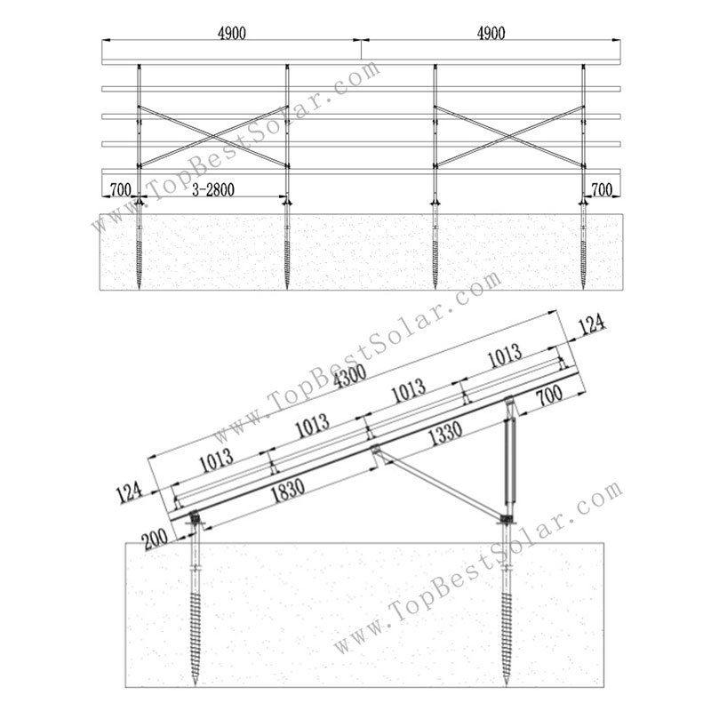
Step 6 Determine the position of the beam on the purlin
According to the construction drawings, first connect two L4900 rails according to the above rail connection method. Then the cantilever is exposed by 700mm, and the distance between the front and rear of the purlin is 124mm, and then install a whole rail at an interval of 1013mm. The fixing method of the beam and the purlin .
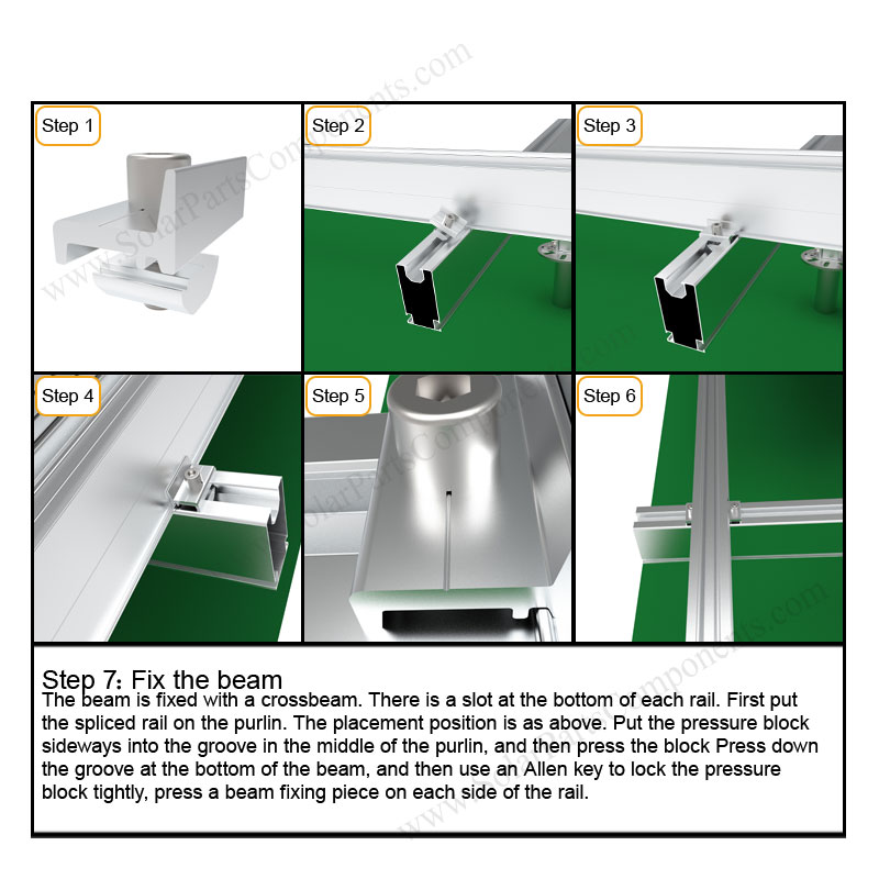
Step 7 Fix the beam
The beam is fixed with a crossbeam. There is a slot at the bottom of each rail. First put the spliced ??rail on the purlin. The placement position is as above. Put the pressure block sideways into the groove in the middle of the purlin, and then press the block Press down the groove at the bottom of the beam, and then use an Allen key to lock the pressure block tightly, press a beam fixing piece on each side of the rail
After the beam is fixed.
Fix the remaining 4 splicing rails on the purlins according to the above installation steps.
Step 8 install solar panels
According to the construction drawings, we can see that the solar panels are placed horizontally on the rail, from bottom to top, from right to left, or in the opposite direction. The solar panel frame on the outermost side exposes the rail 45mm, and the distance between the horizontal panels is 10mm. The position of the mid /end clamp is 940mm in the center, or adjust the position of the mid /end clamp according to the site
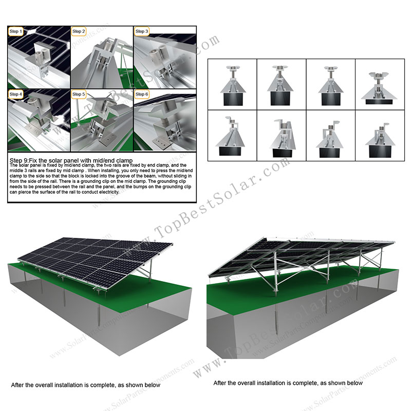
Step 9 Fix the solar panel with mid/end clamp
The solar panel is fixed by mid/end clamp, the two rails are fixed by end clamp, and the middle 3 rails are fixed by mid clamp . When installing, you only need to press the mid/end clamp to the side so that the block is locked into the groove of the beam, without sliding in from the side of the rail. There is a grounding clip on the mid clamp. The grounding clip needs to be pressed between the rail and the panel, and the bumps on the grounding clip can pierce the surface of the rail to conduct electricity.
Step 10 Fix the grounding clip
Use self-tapping screws to fix the grounding clip on the bottom of the rail, install one on each beam, and install each grounding clip in the same position. Then pass the copper wire through all the grounding clips, tighten the M6 ??bolts on the side of the grounding clip, fix the copper wire on the grounding clip, and finally lead the copper wire into the ground.
After the overall installation is complete.
- Installation
-
Installation steps for solar ground mount racking, SPC-GA20-4H-CA:
Step 1: Pre-assembly and installation of purlin.
When shipping, the factory has pre-assembled the purlin, jackets, columns, and grounding screws with bolts. After the bracket arrives on site, only need to open the pre-assembly, rotate the square tube in the direction on the drawing, and then remove the pre-assembled Bolts, lock the square tube on the base, and finally tighten all the bolts with a torque wrench.
Step 2: Fix the purlin pre-assembly
Put the assembled purlin pre-assembled on the ground screw, and install the pre-assembled base on the ground screw with M12*40 bolts.
Note: After installation, the front and rear columns are vertical to the ground. The connecting bolts of the front and rear columns and the base are at the lowest point. Try to make the bottom of the column contact with the base, so that the force on the bracket can directly act on the grounding screw. This position can also be adjusted when the upper surface of the purlin is not in the same plane.
Step 3 Adjust the purlin pre-assembly
According to the above steps, all the purlins are pre-assembled and installed on the ground screws. Note that after all the purlins are pre-assembled and installed on the ground screws, the front ends of the purlins must be on the same line. If they are not on the same line, you can Loosen the bolts fixed to the ground screws on the base, and fine-tune the entire purlins before and after pre-assembly, the upper surface of the purlin also needs to be on the same plane. If it is not on the same plane, you can loosen the bolts connecting the square tube to the base and fine-tune the pre-assembled bracket up and down.
Step 4 install aluminum edge column
The aluminum edge column is installed on the rear vertical support square tube. The rear vertical square tube has pre-drilled holes. The aluminum edge column is fixed with M10 external hexagonal bolt components.
One square tube is installed on each of the front and back sides, and the two aluminum edge columns are cross-shaped, and one set is installed crosswise every other span.Step 5 splicing beams
The steps of rail connection are as follows:
Step 6 Determine the position of the beam on the purlin
According to the construction drawings, first connect two L4900 rails according to the above rail connection method. Then the cantilever is exposed by 700mm, and the distance between the front and rear of the purlin is 124mm, and then install a whole rail at an interval of 1013mm. The fixing method of the beam and the purlin .
Step 7 Fix the beam
The beam is fixed with a crossbeam. There is a slot at the bottom of each rail. First put the spliced ??rail on the purlin. The placement position is as above. Put the pressure block sideways into the groove in the middle of the purlin, and then press the block Press down the groove at the bottom of the beam, and then use an Allen key to lock the pressure block tightly, press a beam fixing piece on each side of the rail
After the beam is fixed.
Fix the remaining 4 splicing rails on the purlins according to the above installation steps.
Step 8 install solar panels
According to the construction drawings, we can see that the solar panels are placed horizontally on the rail, from bottom to top, from right to left, or in the opposite direction. The solar panel frame on the outermost side exposes the rail 45mm, and the distance between the horizontal panels is 10mm. The position of the mid /end clamp is 940mm in the center, or adjust the position of the mid /end clamp according to the site
Step 9 Fix the solar panel with mid/end clamp
The solar panel is fixed by mid/end clamp, the two rails are fixed by end clamp, and the middle 3 rails are fixed by mid clamp . When installing, you only need to press the mid/end clamp to the side so that the block is locked into the groove of the beam, without sliding in from the side of the rail. There is a grounding clip on the mid clamp. The grounding clip needs to be pressed between the rail and the panel, and the bumps on the grounding clip can pierce the surface of the rail to conduct electricity.
Step 10 Fix the grounding clip
Use self-tapping screws to fix the grounding clip on the bottom of the rail, install one on each beam, and install each grounding clip in the same position. Then pass the copper wire through all the grounding clips, tighten the M6 ??bolts on the side of the grounding clip, fix the copper wire on the grounding clip, and finally lead the copper wire into the ground.
After the overall installation is complete.
Can I have quote for the following solar ground racking systems
Client:
To whom it may concern
Please can I have quote for the following solar ground racking systems?
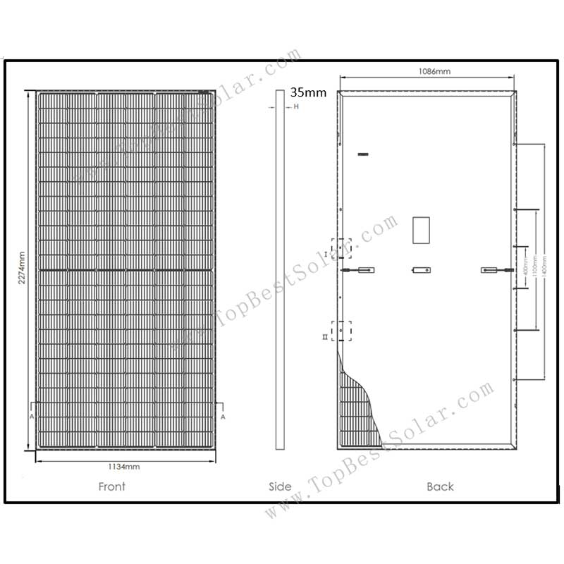
The PV modules specs are the same for each please see figure 1 below.
Figure 1 PV Module Dimensions:
Solar Ground Racking System Panel sizes
SYSTEM 1:
Number of PV Modules: 644
Type: Ground Mount Racking Structures
Table Layout: to be determined (most economical)
Angle: 20 or 15 deg What ever is cheaper.
VAT
Please Exclude VAT as these will be exported from South Africa.
Do you have a SADAC certificate? This allows us to not pay duty when bringing them into Zambia.
Kind Regards
Alexander Siddle
Answer:
Hi Alex
Appreciated for inquiry about our solar rack mounting system.
I will let our engineer working on them in 2-3 working days.
Before design & quotation I need more info from you.
What’s the budget for them? USD/Watts.
(1)Information of your PV panels
1. Dimension: 2274 mm Length x 1134 mm Width x 35mm Thickness,
2. Array: ________Nos. in a row x________Nos. in a column;
3. Horizontal or Vertical?
(2) How is weather there,such as wind speed and snow load?
___m/s anti-wind speed and____KN/m2 snow load.
(3) Tile Angle of your panels mounting
(4) Clearance height from the ground
(5) VAT
Please Exclude VAT as these will be exported from South Africa.
Do you mean the price term is EXW (factory), right?
(6)SADAC Certificate
We have no this certification but we can assist with you to get it.
Is the official web as below?
http://sars.gov.za
Following is our initial design for 4X23-W ground mounts:
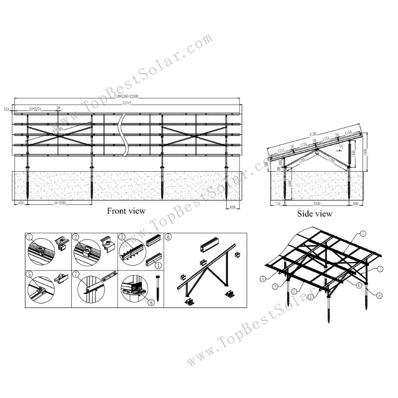
Solar Ground Racking System Design
Let me know if you need any modifications.
Yours early reply would be grateful!
Solar Ground Rack System Factory
- FAQ
-
Can I have quote for the following solar ground racking systems
Client:
To whom it may concern
Please can I have quote for the following solar ground racking systems?
The PV modules specs are the same for each please see figure 1 below.
Figure 1 PV Module Dimensions:
Solar Ground Racking System Panel sizes
SYSTEM 1:
Number of PV Modules: 644
Type: Ground Mount Racking Structures
Table Layout: to be determined (most economical)
Angle: 20 or 15 deg What ever is cheaper.
VAT
Please Exclude VAT as these will be exported from South Africa.
Do you have a SADAC certificate? This allows us to not pay duty when bringing them into Zambia.
Kind Regards
Alexander SiddleAnswer:
Hi Alex
Appreciated for inquiry about our solar rack mounting system.
I will let our engineer working on them in 2-3 working days.
Before design & quotation I need more info from you.
What’s the budget for them? USD/Watts.
(1)Information of your PV panels
1. Dimension: 2274 mm Length x 1134 mm Width x 35mm Thickness,
2. Array: ________Nos. in a row x________Nos. in a column;
3. Horizontal or Vertical?(2) How is weather there,such as wind speed and snow load?
___m/s anti-wind speed and____KN/m2 snow load.(3) Tile Angle of your panels mounting
(4) Clearance height from the ground
(5) VAT
Please Exclude VAT as these will be exported from South Africa.
Do you mean the price term is EXW (factory), right?
(6)SADAC Certificate
We have no this certification but we can assist with you to get it.
Is the official web as below?
http://sars.gov.za
Following is our initial design for 4X23-W ground mounts:
Solar Ground Racking System Design
Let me know if you need any modifications.
Yours early reply would be grateful!
Solar Ground Rack System Factory